Sandwich Type Radiant Floor (General)
The sandwich type radiant floor construction method is one which I have been promoting vigorously for many years now. It is simply the best method for most suspended floors and just about all retrofit applications in residential buildings. This method of constructing a radiant floor, involves placing a ¾ inch nominal subfloor (Normally Oriented Strand Board (OSB), in strips over the existing floor, providing a series of ¾ inch grooves, wherein the ‘Omega Style” aluminum heat transfer plates are installed and the tubing placed within the plates.
This method is extremely versatile, in that it allows absolute freedom to lay the tubing matrix exactly as needed to address the heat loss of the room. Unlike the placing of tubing and plates under the floor in the joist cavity, this sandwich method is not impeded by the orientation of the joists.
The sandwich method provides some of the most efficient energy transfer from the tubing to the surface of the floor. Since the major surfaces of the aluminum heat transfer plates reside on the top of the subfloor, there is much less resistance to heat transfer, than other methods, such as placement below the subfloor and/or underlayment. ” . Wood is, in fact, somewhat of an insulator. I’ve often said “They used to put wood handles on frying pans because they didn’t conduct heat”. That insulating affect improves the performance of the sandwich radiant floor, to the extent that downward losses are reduced significantly to the extent that, for most installations, no additional insulation is necessary.
I have outlined some specific instructions for placing a sandwich type radiant floor over existing subfloors and concrete slabs in the subsequent pages on my website. This discussion is more general in nature, and should apply to any sandwich method used.
As usual, I highly recommend that, before any making any specific decisions regarding your project, a complete heat loss analysis be performed on each room, individually, in order to determine how much energy will be needed and at what supply water temperature. The project needs to be within the limitations of the radiant floor and its capacity to deliver heat.
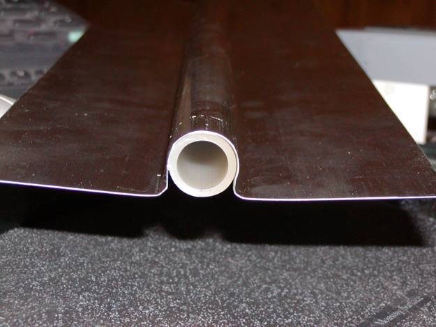
The “Omega” style aluminum plates, that I provide, are designed to grip the tubing once it is placed in the groove. This is the only type plate that is useful in the sandwich type construction method. The 0.018 inch thickness lays close to the top of the subfloor groove and does not disrupt the laying of subsequent finished floor products.
Normally, I calculate one plate per two square foot of floor surface for 12 inch on center projects, one plate for 1.5 square feet on 9 inch on center projects and one plate per square foot on 6 inch on center projects. The plates are 18 inches in length. I find this to be the most practical length for the sandwich method. With this length, I am most often able to come up with a good saturation of plates where I need them. Longer lengths result in having to cut plates more often in order to get enough plates in the groove. I cut the plates on my miter saw with a carbide blade by stacking about 5 plates at a time and moving the blade very slowly through the aluminum. I, typically, stop the blade below the cutting surface before raising it back up. Obviously, I would recommend serious eye protection and gloves to prevent injury during this process.
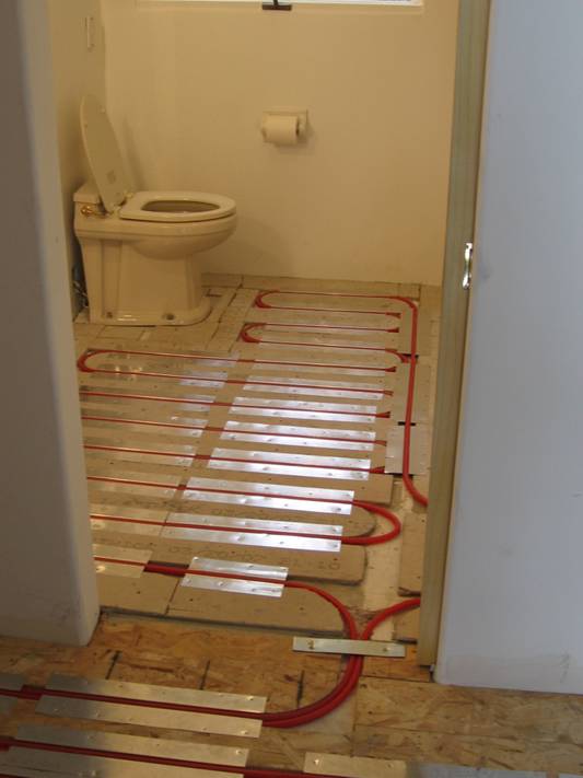
Typically, most of the heat loss occurs very close to outside walls, and, particularly, in close proximity to windows and doors. We place the aluminum plates very close together in these regions, leaving only an inch or so between the ends of the plates. As we get further away from the outside walls, we place the plates a bit further apart because the heat loss there is not as great.
For high temperature heat plants, such as boilers or water heaters, we can place the tubing at 12 inches on center, and 6 inches on center near high heat loss areas, such as glass doors and large windows.
For low temperature heat plants, such as geothermal heat extractors (water to water heat pumps) we often need to place the tubing at either 9 inches on center, or 6 inches on center, depending on the heat loss.
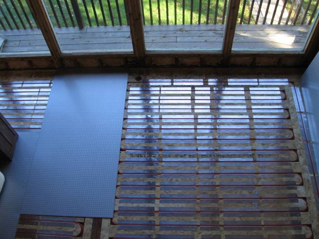
This method is very compatible with most finished floors. We place tile backer board over the subfloor where tile will be installed. We typically place a thin subfloor in areas where carpet will be installed. I’ve found that high density ¼ inch “Pegboard” is particularly suitable for areas that will be carpeted. The holes in the pegboard provide a visual clue as to where the tubing is (or isn’t) so that screws or staples will not likely puncture the tubing. And, the holes in the peg board provide a good countersink for bugle head deck screws. If a hardwood finished floor is to be installed, I normally politic for the use of an engineered wood floor product. Engineered hardwood floors consist of wood layers that are biaxially oriented, like plywood so that they are much more dimensionally stable than solid hardwood. They are also much thinner than solid hardwood so that they transfer heat more efficiently. Lastly, engineered wood flooring is usually finished more effectively than solid hardwood and it resists the affects or moisture better. With engineered flooring, we, typically use come construction adhesive between the finished floor and the OSB subfloor, which gives the finished floor a much more solid feel. Solid floors are normally nailed to the subfloor with extreme caution to prevent nail damage to the tubing. It is helpful that the tubing is exposed to the vision of the installer during this process. Nonetheless, there have been accidental punctures even so. If sheet goods are to be placed as the finished floor, we normally install a thin layer of luan plywood or tile backer over the plates to provide a smooth surface for the sheet goods.
As with any construction discipline, there are many “tricks of the trade” that make for improved installation and performance. Thankfully, with this method, the learning curve is very low. Good quality tools make a big difference. Incidentally, I believe that one reason this method is not altogether popular with “professional heating contractors” is that they do not, normally, use wood working tools in their profession. This method is, however, very much within the capacity of a general contractor or Do It Yourself (DIY) homeowner.
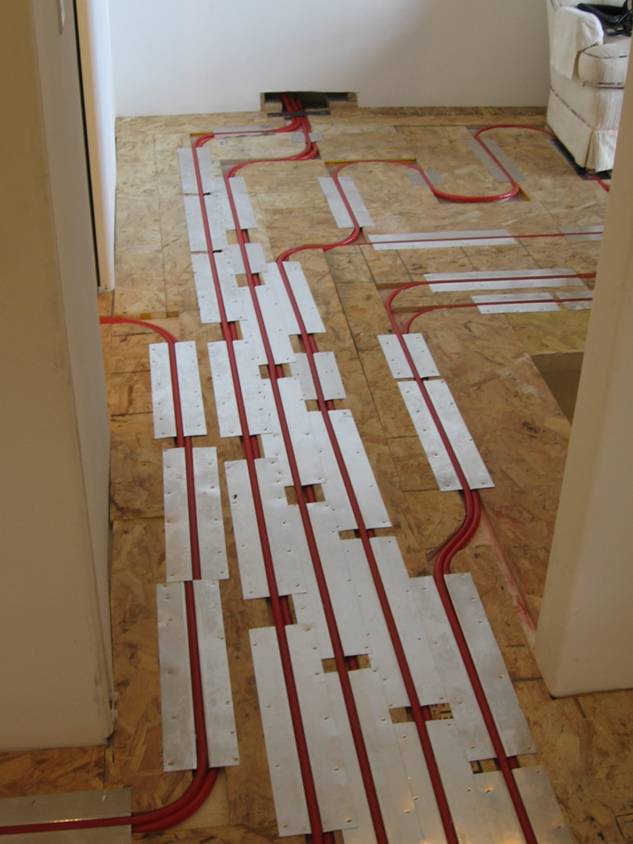
If the sandwich method is to be applied above an unfinished basement, we find it useful to make our tubing runs to the loop underneath the subfloor and come up within the layout groove where we drill two ¾ inch holes about 3 inches apart and use our saber saw (jig saw) to cut out the space between the holes, making an oblong hole for the tubing to penetrate the subfloor.
If we need to make all runs on the surface of the floor, we often find that it is difficult to fit all the runs through a hallway or door. In order to accommodate several runs, we often place the supply and return in the same “double groove”, with the plate being offset to one side of the groove and placed over one pipe and under the other.
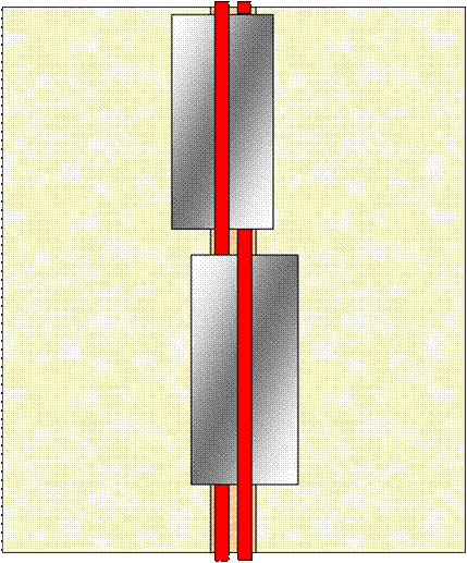
The picture below demonstrates this and speaks volumes for the versatility of the sandwich radiant floor construction method. This is one of the most efficient, least costly and least intrusive construction methods. It can be used in new construction or in retrofit applications on suspended or concrete on grade floors with just about any floor covering. It requires no special equipment and can be done with simple tools. Contact me directly tom@tesmar.com for further information and assistance.